Designing Cabling Infrastructure for Ever-Increasing Data Speeds
Design a cabling system to
support ever-increasing data speeds
Data speeds are ever-increasing and the need for bandwidth is never satisfied. With the next jumps in speed only just around the corner, the need to support these speeds requires critical fiber cabling considerations. Implementing a properly planned structured cabling system to accommodate multiple upgrades well into the future is important. For this to be done properly, there are many considerations to be made. Here are the key ones:
Understanding data transmission
The partnership between fiber optics and cabling is an important concept to understand when it comes to transmission speeds. Firstly, the active optics (the hardware components that the cabling plugs into) are what drives the data transmission. Therefore, the cabling is a passive component. It has the role of carrying that data from transmitter to receiver. The active hardware and passive components create a partnership that needs to work in concert, and there are standards bodies that provide the roadmap in order to accomplish this.
The next concept to understand is that there are two primary data transmission protocols used in the active hardware for data center connectivity. Ethernet, which is widely used in network connectivity, and Fiber Channel, which is used for data storage (SAN) connectivity.
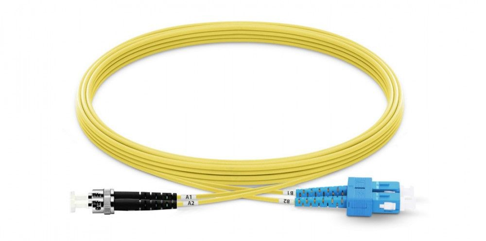
Finally there is 'serial' vs 'parallel' transmission. Serial, or 'duplex' transmission, uses a single fiber to transmit data, and a single fiber to receive data. Using multi-mode, single fibers the properties of this fiber type have a limited amount of data that can be transmitted without errors occurring. This necessitates the development of another transmission method, parallel transmission. Parallel transmission divides the signal at transmission and re-assembles it at the receiver (called multiplexing), thus allowing higher transmission speeds over multi-mode fiber. This is currently not necessary for single-mode fiber, as its carrying capacity (bandwidth) for data is so much higher.
Standards bodies
As mentioned above, standards bodies provide the protocols and roadmaps for designing a structured cabling system. Here are some important points:
Figure 1

TIA Standard
The Telecommunications Industry Association (TIA) is an organization that is important to consider when designing a structured cabling system. The TIA has many published standards that will aid with design (see Figure 1).
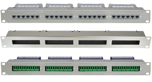
For example, the TIA-942-B standard (named Commercial Building Telecommunications Cabling Standard) shows how to deploy a structured cabling solution with the use of patch panels, conveyance pathways, and proper cabinets, as shown in Figure 2 below.
The TIA-568.3-D standard shows the polarity (light path) options when using an MPO/MTP connector, which is used in the latest Ethernet and Fiber Channel optics.
Understanding these light path options is an important aspect.

Figure 2
T11 Technical Committee
The T11 Technical Committee for Fiber Channel Protocol released Generation 7 optics doubling the speed of Generation 6 speeds, going from 32 Gb/s to 64 Gb/s on duplex (or two fibers) and 128 Gb/s to 256 Gb/s on parallel (or eight fibers).
IEEE Standard
The Institute of Electrical and Electronics Engineers (IEEE) released the 802.3bs for the Ethernet protocol as Physical Layers and Management Parameters for 200 Gb/s and 400 Gb/s operations.
This new standard increased the speed per fiber strand from 25 Gb/s to 50 Gb/s on multi-mode glass. It also introduced a new singlemode optic that reduced the maximum distance from 2km to 500 meters. This reduction in the maximum distance also reduced the cost of the optic.
In summary, plan for a structured cabling system to work with both duplex (LC connector) and parallel (MPO connector) optics. This will be needed to migrate to higher speeds that require parallel transmission for multi-mode fiber, and it's an important consideration that affects both cost and flexibility. For distances under 100 meters, use at least OM4-related multi-mode glass. For distances over 100 meters, consider single-mode glass to distances up to 500 meters.
Plan for patch panels at the core, director, or spine switches so you have the ability to plug in both duplex and parallel optics. The break the patch panels provide in the link near these switches allows the horizontal or backbone cabling to remain in place for multiple generations of optics moving forward. Having a break in the link at the other end, typically a server connection allows the ability to plug in both duplex and parallel optics on the end. It also allows the user to break out connections on the Server side, ie 100G into 4 x 25G.
Optical loss budgets and polarity
Patch panels add flexibility to the structured cabling design, but inherently introduce optical loss at each interconnect point. Having these interconnect points is essential to support duplex and parallel optics. The optical loss incurred from the use of patch panels should not exceed allowable light budgets in order to support current and next generation optics. To ensure this, it is important to understand the maximum allowed loss of cabling products that are specified for the cabling infrastructure.
Figure 3

Figure 4

Adding patch panels into your design, as well as the ability to connect both duplex and parallel optics, will provide some challenges to be aware of when it comes to inter-connect loss considerations. Keep in mind also that you will need to keep the interconnect loss below 1.5dB to keep the loss within specification for both the latest Ethernet and Fiber Channel standards. You will also need to consider the TIA-568.3-D document to decide what MPO/MTP polarity option to select to best support the new design. Polarity is critical in cabling systems in order to assure that data transmissions are received by the appropriate receivers. There are three methods described in the standard as Method A, B and C, all of which have their advantages and disadvantages.
Adding patch panels into your design
There are two schools of thought when it comes to patch panel sizes. The first is to pack as many ports as possible into a rack unit. This option works well when at the initial time of installation all of the ports are connected and the patch panel can be closed and the cabling can be dressed once and left alone. Selecting the best size and port count patch panel for the switch greatly helps manage the connectivity.
If you are requiring distances over 100-150 meters, look to singlemode fiber and a PSM-4 optic. Consider pricing singlemode optics to determine if installing singlemode fiber will set the data center up for next generation gear seamlessly.
Another consideration for the size of your patch panel, is whether to use port replication. Port replication is 'mirroring' the ports of active fiber optic hardware in a passive component (fiber patch panel). This creates a direct, one-to-one relationship between the active hardware ports and the passive structured cabling environment, thus simplifying the cabling process as all numbers on the hardware directly correspond to the numbers on the patch panel.
Design considerations
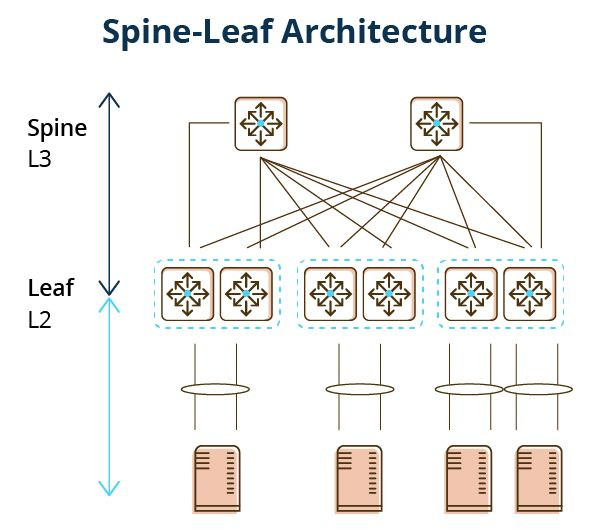
Traditionally, a 'three-tier' design has been the standard and has been dominant for decades. However, a 'spine-and-leaf' design has been used more recently, allowing for a number of benefits.
A spine-leaf architecture is data center network topology that consists of two switching layers—a spine and leaf. The leaf layer consists of access switches that aggregate traffic from servers and connect directly into the spine or network core. Spine switches interconnect all leaf switches in a full-mesh topology.
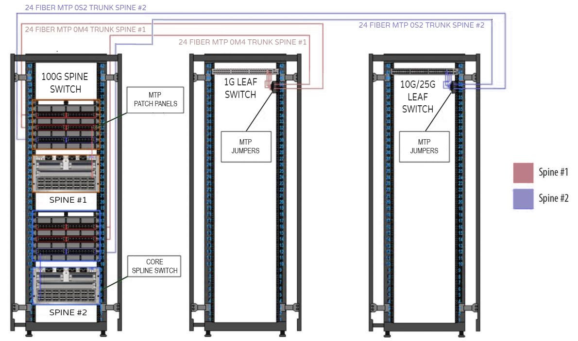
Using the illustration above, the MPO panels over each core switch allow either an LC to MPO or MPO to MPO cable to be installed to connect a duplex or parallel optic. There are enough ports in the patch panels to support full growth of the chassis. The MPO to MPO fiber trunking goes out into the data center floor and can stay in place when new switches are installed, and the old switches can be removed one fabric at a time.
Conclusion
The IEEE standard for Ethernet and T11 standard for Fiber Channel defines the amount of allowable loss in the cabling system. Loss must be under the allowed budget in order to maintain proper operation. Loss amounts must be considered when choosing cabling and patch panel products, as the highest loss amounts occur here. Compare the amount of allowable loss with the maximum loss amount of your selected cabling products in order to ensure those budgets are met.
The TIA-942 standard offers multiple polarity options, which provide guidance for proper signal transmission and reception. With the current direction of hardware offerings, using both LC and MTP ports, the ideal option will allow for a seamless and cost-effective transition between the two connector types. The overall design will be a key consideration. Whether you choose a traditional three-tier topology, or a spine-and-leaf design, will depend on your overall hardware deployment strategy. This choice will dictate how your structured cabling solution will be implemented.


