Differentiating Return Loss,
Insertion Loss, and Crosstalk
Understanding the behavior of signals in cabling systems requires clarity about insertion loss, return loss, and crosstalk. These phenomena affect signal transmission in different ways and are influenced by various factors, depending on whether the system is fiber optic or copper-based.
Insertion Loss
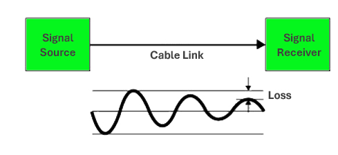
Insertion loss refers to the amount of signal power lost as it travels through a transmission medium, such as twisted pair cabling. It is a critical performance parameter in structured cabling systems because excessive insertion loss can lead to degraded data transmission and network performance.
Definition: The attenuation of signal power measured in decibels (dB) between the input and output of a cable or component.
Measurement Unit: Decibels (dB).
Relevance: Lower insertion loss is better for maintaining signal strength and quality over a distance.
Insertion Loss in Twisted Pair Cabling (e.g., Cat.6)
Twisted pair cabling like Cat.6 is designed to minimize signal loss and interference, but insertion loss still occurs due to various factors. Cat.6 cabling supports high-speed data transmission (up to 10 Gbps for short distances) and operates at frequencies up to 250 MHz.
Factors affecting Insertion Loss in Cat.6 Cabling
Cable Length
- The longer the cable, the greater the insertion loss.
- Cat.6 cables are rated for up to 100 meters, but insertion loss increases significantly beyond this length.
Frequency
- Insertion loss increases with higher frequencies.
- At higher frequencies, more energy is absorbed by the cable materials.
Cable Quality
- Poorly manufactured cables may have higher resistance, poor insulation, or inconsistent twists, leading to greater insertion loss.
Temperature
- Higher temperatures can increase the resistance of the conductors, resulting in more signal loss.
Connectors and Splices
- Each connector or splice adds a small amount of insertion loss.
- Poorly installed terminations can exacerbate this issue.
Signal Reflection
- Impedance mismatches between the cable and connectors can cause reflections, leading to signal loss.
Key Standards for Insertion Loss in Cat.6 Cabling
Industry standards specify acceptable levels of insertion loss for Cat.6 cabling:
- ANSI/TIA-568: Specifies performance criteria for balanced twisted-pair cabling.
- ISO/IEC 11801: International standards for structured cabling systems.
Maximum Insertion Loss (Attenuation) for Cat.6 Cabling typically ranges from 0.15 dB/m at 1 MHz to about 4 dB/m at 250 MHz.
Testing and Measuring Insertion Loss
Setting up the Tester
Use a calibrated tester capable of measuring insertion loss at specified frequencies.
Connecting the Cable
Connect both ends of the cable to the tester.
Running the Test
The tester sends signals of various frequencies through the cable and measures the signal loss.
Interpreting the Results
Results are compared to the standards to determine if the cable meets the performance criteria.
Reducing Insertion Loss in Cat.6 Cabling
Use high-quality Ethernet cables to ensure optimal performance and reliability. Choose cables that meet or exceed Cat.6 standards and are certified by reputable manufacturers that produce durable, industry-compliant networking products. Other considerations include:
Maintain Proper Length
Keep cables under the maximum recommended length (100 meters).
Minimize Connections
Limit the number of connectors and splices in the cabling run.
Ensure Proper Installation
Avoid sharp bends, excessive pulling force, and improper terminations.
Environmental Considerations
Keep cables away from heat sources and ensure they are properly shielded in environments with high electromagnetic interference (EMI).
How are Insertion Loss limits calculated for the standards
Insertion loss (attenuation) refers to the reduction in signal strength as it travels through a cable due to electrical resistance, dielectric loss, and other dissipative effects. It is expressed in decibels (dB) and varies with:
- Frequency (MHz): Higher frequencies result in greater loss.
- Cable Length (meters): Longer cables introduce more loss.
- Cable Construction: Copper conductor quality, insulation, and shielding impact loss.
According to the TIA-568.2-D standard, the insertion loss (IL) for balanced twisted-pair cables is calculated using the following formula:
Where:
- f = Frequency in MHz
- A, B, and C = Constants provided in the standard (specific to the cable type, such as Cat 5e, Cat 6, or Cat 6A)
- The formula calculates the loss per 100 meters, and the value is scaled based on the actual cable length.
For a shorter length L, the formula is adjusted as:
The constants A, B, and C are empirical coefficients that represent the contribution of different physical factors affecting signal attenuation in the cable. Their meanings are:
- A : Represents the primary frequency-dependent loss, primarily due to the resistive and inductive components of the cable.
- It scales with the square root of the frequency √(f) reflecting how attenuation increases with frequency due to skin effect and inductive losses.
- B : Represents the linear frequency-dependent loss, which accounts for dielectric losses within the insulation materials of the cable.
- This term scales directly with frequency (f), meaning higher frequencies result in proportionally higher loss.
- C : Represents the constant loss term, which accounts for minor, frequency-independent losses due to imperfections in the cable, connectors, or environmental factors.
- For Cat 6 cables, this value is negligible and is typically considered zero.
These coefficients are derived from industry-standard measurements and modeling under specific conditions, and they provide an approximation of real-world insertion loss for a given frequency and cable length.
Typical Constants for Cat 6 Cables (from TIA-568.2-D)
For Category 6 cables, the TIA standard specifies the following empirical coefficients:
- A=1.967
- B=0.023
- C=0 (negligible)
Thus, the formula simplifies to:
Example Calculation for Cat 6 at 100 MHz (50 meters)
Imagine a 50-meter Cat.6 cable run supporting a 1 Gbps Ethernet connection. If the insertion loss at 100 MHz is 21 dB for 100 meters, then for 50 meters:
Given:
- Frequency f = 100MHz
- Cable length L=50 meters

This value should be within the acceptable range specified by the standards.
Return Loss
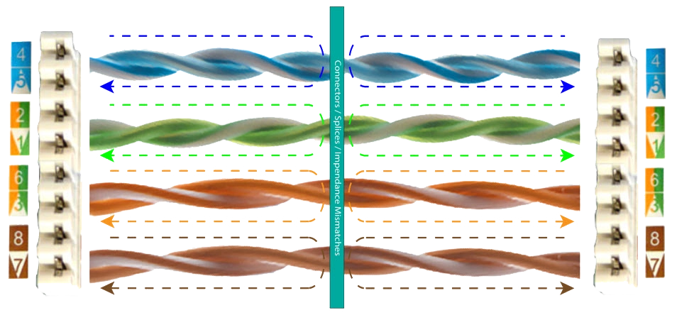
Return loss measures the amount of signal power that is reflected back toward the source due to impedance mismatches in the transmission medium. It is an important parameter in twisted pair cabling systems because excessive reflection can interfere with the original signal and reduce the efficiency of data transmission.
- Definition: The ratio of the power of the transmitted signal to the power of the reflected signal, in decibels (dB).
- Measurement Unit: Decibels (dB).
- Relevance: A higher return loss (in dB) indicates better performance, as it signifies minimal signal reflection.
Return Loss in Twisted Pair Cabling (e.g. Cat.6)
Cat.6 twisted pair cabling is designed to minimize reflections by maintaining consistent impedance and precise twisting of pairs. High-quality Cat.6 cabling ensures low return loss, supporting reliable high-speed data transmission.
Factors Affecting Return Loss in Cat.6 Cabling
Impedance mismatch, caused by deviations from the nominal impedance (such as 100 ohms for twisted pair cables), can result in reflections and may arise from poor manufacturing, improper terminations, or incompatible components. Other factors include:
Cable Quality
Connectors and Terminations
- Poorly constructed cables with irregular twisting or inconsistent insulation can result in greater impedance variations, leading to increased return loss.
- Improperly installed or substandard connectors can cause discontinuities in impedance
- Loose or untwisted terminations are common culprits.
Frequency
Cable Length
- Return loss decreases (worsens) at higher frequencies, as even small impedance mismatches become more significant.
- Longer cables can amplify the effects of impedance mismatches.
Key Standards for Return Loss in Cat.6 Cabling
Industry standards define acceptable return loss levels to ensure optimal performance:
- ANSI/TIA-568: Specifies return loss requirements for twisted pair cabling.
- ISO/IEC 11801: Defines international performance standards for structured cabling.
For Cat.6 cabling:
- Return Loss Requirements:
- At frequencies up to 100 MHz, return loss should be >=20 dB.
- At higher frequencies (e.g., 250 MHz), it should be >=10 dB.
Testing and Measuring Return Loss
Return loss is typically measured using a cable certifier or network analyzer.
Set up the Tester
Initiate Testing
Interpret Results
Connect both ends of the cable to the testing equipment.
The tester sends a signal through the cable and measures the power of the reflected signal.
The results are displayed in dB, with higher values indicating better performance.
Compare the measured values to industry standards.
The Impact of Poor Return Loss
Signal Interference
Reduced Data Rates
Bit Errors
- Reflected signals can interfere with the transmitted signal, causing errors.
- High return loss can lead to reduced network speeds, especially at high frequencies.
- Excessive reflections increase bit error rates (BER), compromising data integrity.
How to Minimize Return Loss in Cat.6 Cabling
Use High Quality Materials
Ensure Proper Installation
Proper Termination
- Select cables and connectors that meet or exceed Cat.6 standards.
- Avoid sharp bends, excessive pulling, and kinks during installation.
- Maintain the twists of each pair as close to the termination point as possible.
- Use appropriate tools to terminate cables accurately.
- Verify that all connections are secure and compliant with the manufacturer’s specifications.
Avoid Mixed Components
Testing and Certification
- Select cables and connectors that meet or exceed Cat.6 standards.
- Avoid sharp bends, excessive pulling, and kinks during installation.
- Maintain the twists of each pair as close to the termination point as possible.
Return Loss in Different Cable Categories
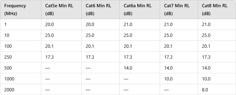
The ANSI/TIA-568 standards specify minimum return loss values for various cable categories. While specific empirical formulas for each category may not be publicly detailed, the standards provide minimum return loss values at designated frequencies. Below is a summary of typical minimum return loss values for Cat5e, Cat6, Cat6a, Cat7, and Cat8 cables:
Practical Example
Imagine a 90-meter Cat.6 horizontal cable run installed in an office building. During testing, the return loss at 100 MHz is measured as 18 dB. This is below the standard of >=20 dB, indicating a potential problem.
Possible Issues:
- Impedance mismatches due to improper terminations.
- Poor-quality connectors or damaged cables.
Solution:
- Recheck terminations, ensure they are properly made.
- Replace substandard or damaged components.
Comparison Between Insertion Loss and Return Loss
Aspect | Insertion Loss | Return Loss |
|---|---|---|
Definition | Measures transmitted signal attenuation | Measures reflected signal power |
Impact | Signal weakens over distance and frequency | Reflections interfere with the signal |
Ideal Value | Lower (e.g. < 20dB for 100 meters at 250 MHZ) | Higher (e.g. ≥20 dB) |
Cause | Cable length, frequency, temperature | Impedance mismatches |
Near-End Crosstalk (NEXT)
NEXT in Twisted Pair Cabling (e.g., Cat.6)
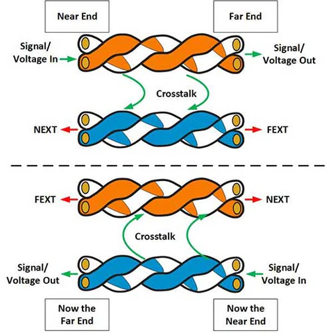
Near-End Crosstalk (NEXT) measures the interference caused when a signal transmitted on one pair of wires in a cable induces unwanted signals in another pair. The term "near-end" refers to measurements taken at the same end of the cable where the signal is being transmitted.
Definition: NEXT quantifies how much of the signal transmitted on one wire pair leaks into another wire pair at the same end of the cable.
Measurement Unit: Decibels (dB), representing the ratio of the transmitted signal power to the induced signal power.
Relevance: A higher NEXT value (in dB) indicates better performance and less interference.
Factors affecting NEXT in Cat.6 Cabling
Twist Rate
Each pair of wires is twisted at a specific rate to reduce Crosstalk.
Variations in the twist rates between pairs minimize electromagnetic coupling.
Cable Quality
Poor-quality cables with inconsistent twist patterns or inadequate insulation can have higher NEXT levels.
Frequency
NEXT becomes more pronounced at higher frequencies, as the coupling between pairs increases.
Connector Design
Poorly designed connectors can cause increased Crosstalk at the termination points.
Installation Practices
Untwisting wires too far during terminations increases the likelihood of Crosstalk.
Bundling cables too tightly can also exacerbate NEXT.
Key Standards for NEXT in Cat.6 Cabling
Industry standards define acceptable NEXT levels to ensure reliable data transmission:
ANSI/TIA-568: Specifies minimum NEXT performance requirements for structured cabling.
ISO/IEC 11801: Sets international standards for NEXT in twisted pair cables.
For Cat.6 cabling:
- NEXT values are measured across frequencies, with stricter requirements for higher frequencies.
- A typical requirement is >=39 dB at 100 MHz for a 100-meter cable.
Testing and Measuring NEXT
NEXT is measured during cable certification using specialized equipment.
Set up the Tester
Connect the cable to the certification tester, ensuring proper connections at both ends.
Run the Test
The tester sends a signal down one pair and measures the crosstalk induced in adjacent pairs at the same end of the cable.
Analyze Results
Results are displayed in dB, with higher values indicating less crosstalk and better performance.
Compare results to the standards for Cat.6 cabling.
Impact of Poor NEXT Performance
Signal Degradation
Reduced Data Rates
Increased Errors
High crosstalk can interfere with the transmitted signal, reducing its clarity.
Excessive NEXT limits the cable’s ability to support high-speed data transmission.
Crosstalk can lead to packet loss and higher bit error rates (BER).
How to Minimize NEXT in Cat.6 Cabling
Use High-Quality Components
Select cables and connectors that meet or exceed Cat.6 standards.
Ensure Proper Installation
Maintain the twists of the pairs as close as possible to the termination points.
Avoid tight bends or excessive pulling during installation.
Minimize Untwisting
Keep untwisting of pairs to less than 0.5 inches (1.27 cm) during termination.
Avoid Over-Bundling
Do not bundle cables too tightly, as this can increase the coupling between pairs.
Test and Certify
Test the installation for NEXT compliance using a cable certifier.
Practical Example
Imagine a 90-meter Cat.6 cable run in an office building. During testing, NEXT at 100 MHz is measured as 35 dB, which is below the standard of >=39 dB.
Possible Causes:
- Over-untwisting of pairs during termination.
- Substandard or damaged cables/connectors.
Solution:
- Recheck terminations and re-terminate if necessary.
- Replace any poor-quality components.
NEXT vs Far-End Crosstalk (FEXT)
Aspect | NEXT | FEXT |
|---|---|---|
Definition | Crosstalk measured at the same end of the cable | Crosstalk measured at the far end of the cable |
Impact | Primarily affects transmitter performance | Primarily affects receiver performance |
Mitigation | Use tight twists and proper terminations | Use proper shielding and cable separation |
Wrap-up
Understanding insertion loss, return loss, and crosstalk is essential for maintaining the integrity and performance of modern communication networks. These metrics provide valuable insights into the efficiency and reliability of signal transmission, helping technicians identify and address potential issues before they impact system performance.
By using high-quality components, such as DINTEK cables, following best installation practices, and employing regular testing with specialized equipment, network designers and installers can ensure that cabling systems meet industry standards and deliver optimal performance. DINTEK cables are renowned for their exceptional build quality, rigorous compliance with international standards, and advanced shielding technologies that minimize signal degradation and interference. Our superior materials and precision engineering result in reduced insertion loss, enhanced return loss characteristics, and minimized crosstalk, ensuring high-speed data transmission with unwavering reliability.
Investing time in proper planning, testing, and mitigation not only extends the lifespan of the cabling infrastructure but also ensures a seamless and reliable experience for end users in an increasingly connected world. With DINTEK cables, businesses and organizations can trust that their network infrastructure is built to withstand the demands of modern connectivity, delivering consistent, high-performance results across a variety of applications.
Send a message for more information.
