Understanding Fiber Optic Distance Limits in Network Design
Fiber Optic Series:
Calculating distance limits and fiber optic loss
One of the critical factors influencing the performance of fiber optic networks is the attenuation of signals, commonly known as fiber optic loss. This loss, along with other factors, imposes distance limits on the transmission of data through optical fibers.
In this article, we'll explore the concepts of fiber optic loss and distance limits and how they affect the design and efficiency of communication networks.
Fiber Loss Budget
Fiber losses result from a combination of inherent and external factors. Fiber loss, also referred to as signal loss or fiber attenuation, stems from both intrinsic and extrinsic characteristics found in single-mode and multimode fibers. To understand how to compute fiber loss in networks, it's essential to take these factors into account. Here are some considerations to factor in when calculating the fiber loss budget:
Intrinsic Attenuation Losses
This term encompasses three distinct types of losses, namely absorption losses, scattering losses, and dispersion losses.
Scattering Losses: These arise from minute variations in compositional fluctuations, material density, manufacturing defects, and structural inhomogeneity. Often, these variations manifest at a microscopic level.
Dispersion Losses: Optical signals may undergo distortion during their passage through the fiber, leading to dispersion losses. Two categories of dispersion losses exist—namely, intra-modal and intermodal. Intra-modal dispersion primarily stems from pulse spreading in a single-mode fiber, attributed to variations in the propagation constant or refractive index along its length. Conversely, intermodal dispersion involves pulse broadening due to propagation delays between different modes in multimode fibers.
Absorption Losses: Identified as a primary cause of optical losses in fiber optic cables, absorption losses result from photon interactions with various glass components, metal ions, or electrons during transmission. This interaction leads to the absorption of light, converting it into other energy forms such as heat, wavelength impurities, and molecular resonance.
For multimode fibers of 50/125 µm and 6.25/125 µm, the intrinsic attenuation is 3.5 dB/km @ 850 nm. For single-mode fibers of 9 µm, the intrinsic attenuation is 0.4 dB/km @ 1310 nm and 0.3 dB/km @ 1550 nm.
Insertion Losses
Termed as connector losses, these refer to the reductions in light power that occur when a device is inserted into an optical fiber or transmission line. Typically, pre-assembled single-mode connectors exhibit losses ranging from 0.1 to 0.2 dB, while field-terminated connectors may incur losses as high as 0.2 to 1.0 dB. For multimode connectors, losses typically fall within the range of 0.2 to 0.5 dB.
Fiber Type
The majority of networks employ either single-mode or multimode fibers, and in many cases, a combination of both. Multimode fibers typically exhibit a loss factor of 2.5 dB/km at 850nm and 0.8 dB/km at 1300 nm. In contrast, single-mode fibers have a lower loss factor of 0.25 dB/km at 1550nm and 0.35 dB/km at 1310nm. Single-mode fibers are well-suited for compatibility with LASER transmitters, available in both short-reach and long-reach configurations. On the other hand, multimode fibers are commonly paired with LED transmitters, particularly for shorter distances not exceeding 1 km due to power limitations. Single-mode fibers are capable of accommodating high-power LED transmitters.
Fiber Loss Factor
Manufacturers typically specify the loss factor in dB per kilometer. The calculation of the fiber loss factor is straightforward—simply multiply the loss factor by the total length of the fiber optic cable. It's important to note that this distance refers to the entire length of the cable, encompassing its total span rather than just the network distance.
Transmitters
LASER transmitters and LED transmitters constitute two crucial types of transmitters employed in the majority of fiber optic networks. LASER transmitters are categorized into three types: low, medium, and high, alternatively referred to as short-reach, medium-reach, and high-reach transmitters. LED transmitters are offered in standard and high-power variants. The optimal choice of transmitters depends on the specific type of fiber being used. When selecting these transmitters, it is essential to emphasize the light output at the connector. Typically, -5dB is a common light output level. It's worth noting that a transmitter is also known as an emitter.
Splicing
Splicing is a process employed to connect two ends of optical fibers, ensuring that the transmitted light through the cable remains as potent as it would in a single fiber. There are two crucial types of splices in fiber optic cable networks: mechanical and fused. Mechanical splices utilize connector sets on the fiber ends, while fused splices involve directly mating the fiber ends. The loss in mechanical splices typically falls within the range of 0.1-1.5 dB per connector, whereas fusion splices exhibit a lower loss factor, ranging from 0.1-0.5 dB per splice. Due to their reduced loss, fused splices are commonly preferred in practical applications.
Margin
This factor holds significant importance. Designing a system is not merely about reaching a receiver with the minimum required light. The light power budget margin takes into consideration various factors such as fiber aging, aging of transmitter and receiver components, addition of devices along the cable path, unintentional twisting and bending of the fiber cable, and additional splices required for cable repairs. Typically, most system designers incorporate a loss budget margin ranging from 3 to 10 dB.
Fiber losses calculation
There are various methods available for calculating fiber loss and assessing the power needs of a specific fiber optic connection. The most straightforward and precise approach to calculate fiber loss is by conducting an Optical Time Domain Reflectometer (OTDR) trace on the given link.
Performing an OTDR trace provides accurate loss values for all components (such as connectors, splices, and fiber loss) within the link. In situations where an OTDR trace is unavailable, two alternative methods can be employed to estimate the power requirements of the link: calculate the overall link loss for a known fiber optic link using the provided fiber length and loss variables; determine the maximum fiber distance achievable when the optical budget and loss variables are known.
Loss variables encompass connectors, splices, and the attenuation per kilometer of the fiber. When the precise values for these loss variables are not available, estimations for each are required to finalize the calculations. In such instances, adopting a worst-case scenario is advisable to ensure sufficient power for the link. The provided table contains widely accepted loss values essential for these calculations:
The following straight-forward formulas are employed to calculate losses across an optical fiber link:
Total Link Loss = Connector Loss + Cable Attenuation + Splice Loss
Cable Attenuation (dB) = Length (km) x Attenuation Coefficient (dB/km)
Connector Loss (dB) = Number of Connector Pairs x Loss Allowance per connector (dB)
Splice Loss (dB) = Number of Splices x Loss Allowance per splice (dB)
It's important to note that the total link loss is the sum of various notable losses within a fiber link. The total link loss calculated is an estimation. The actual loss may vary, being influenced by factors such as operating temperatures, hardware integrity, type of fiber, number of turns, and more.
An example: Let's take into account an optical fiber link comprising a Single-Mode Fiber (SMF) with a length of 8 km, utilizing a 1310nm band for optical transmission. In this hypothetical link, there are 2 sets of ST connectors and 1 splice. According to the standard reference, values chart the light attenuation of 1310nm single-mode optical cable is 0.5dB/km. thus, the total cable attenuation according to the formula is 0.5dB/km x 8km = 4dB.
Applying the maximum values specified by ANSI/TIA, the loss per pair amounts to 0.75. Therefore, the total connector loss in this scenario, as per the formula, is 1.5 dB (0.75 dB multiplied by 2). It is essential in practical calculations to use the values provided by the connector manufacturer.
In this calculation, we will employ the maximum splice loss values outlined by ANSI/TIA, which is 0.3 per splice. Therefore, for this particular link with one splice, the total splice loss, according to the previously mentioned formula, would be 1 x 0.3 dB, resulting in 0.3 dB. As described earlier, the total loss across an optical fiber link can be obtained by summing cable attenuation, splice loss, and connector loss. For this link the total loss is 4dB + 1.5dB + 0.3dB = 5.8dB.
Please note that OTDR tracing of an established optical fiber link is the most accurate and easiest method available for total link loss calculation.
How to reduce fiber optic link loss
The factors above illustrate that fiber optic link loss is influenced by various elements, some of which are challenging to alter. However, certain strategies can be employed to mitigate additional losses and enhance overall link performance:
Opt for high-quality optical fiber and maintain the end face of the fiber flat and clean.
Ensure the technical proficiency of construction personnel to prevent sheath abrasion and excessive bending, coiling, and stretching of fiber optic cables.
Choose high-quality optical transceivers to provide a more stable power budget and extend the overall lifetime of the system.
Minimize the number of unnecessary fiber splices and fusion splice points while keeping connection losses at a minimum. This approach helps reduce additional losses associated with fusion splices and splices at multiple points.
Estimating fiber distance
Estimating fiber distance is an important aspect of planning and deploying fiber optic networks. One commonly used method is the use of the fiber optic link budget to estimate distance. As mentioned above, a link budget is a calculation that takes into account various factors such as transmitter power, receiver sensitivity, fiber attenuation, connector losses, and splice losses to determine the maximum distance that can be achieved with a given set of components.
To estimate fiber distance using a link budget, one needs to consider the characteristics of the specific fiber optic components being used. Transmitter power refers to the strength of the optical signal being transmitted, while receiver sensitivity refers to the minimum power level required for the receiver to detect and interpret the signal. Fiber attenuation refers to the loss of signal strength as it travels through the fiber, and connector and splice losses refer to any losses that occur at connection points along the fiber.
By analyzing these factors and performing the link budget calculation, one can determine the maximum distance that can be achieved with the given components. However, it is important to note that the link budget estimation provides a theoretical maximum distance, and real-world conditions may vary.
This calculation aims to determine the potential maximum distance for a specific fiber optic link based on the optical budget and the quantity of connectors and splices within the link:
Length = ([Power budget] - [fiber loss]) / [loss per km]
or Length = ( [(mininimum TX PWR) - (RX sensitivity)] - [splice loss × qty of splices] - [connector loss × qty of connectors] - [margin] ) ÷ [fiber lost/km]
Scenario: Consider a Single-mode link operating at 1310nm with TX of -7.3dB , RX of -34dB , having 2 connector pairs and 10 splices: The calculated fiber length is determined by the formula:
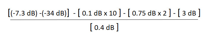
In this scenario, an approximate distance of 53 km can be achieved before reducing the optical power to a level below the Rx sensitivity. It is crucial to emphasize that measuring and confirming the actual link loss values is essential once the link is established, as this helps identify potential performance issues. The actual maximum distances achievable will vary based on factors such as the optical fiber attenuation per kilometer; the design and age of the optical fiber; the caliber of connectors and the actual loss per pair; the quality of splices and the actual loss per splice; the number of splices and connectors in the link.


