Mastering the OTDR:
A Comprehensive Guide to the Optical Time Domain Reflectometer
Optical Time-Domain Reflectometers (OTDRs) are indispensable tools in the field of optical fiber testing and troubleshooting. These devices allow technicians and engineers to accurately measure the characteristics of optical fibers, detect faults, and assess the overall quality of the fiber optic infrastructure. In this guide, we will walk you through the fundamental steps of using an OTDR effectively, helping you unlock the power of this essential instrument.
Understanding the OTDR
Key components
Light Source: The OTDR employs a laser light source, often with tunable wavelengths, to emit optical pulses into the fiber.
Pulse Generator: The pulse generator controls the duration and intensity of the emitted light pulses. Shorter pulses provide higher resolution for detecting smaller events.
Photodetector: A sensitive photodetector captures the reflected signals and converts them into electrical signals for analysis.
Display and Analysis Unit: The collected data is processed and displayed on a screen as a graphical trace. The intensity of reflected light versus time (or distance) is plotted, providing insights into the fiber's characteristics.
A step-by-step guide to using an OTDR
Set Up
Begin by powering on the OTDR and allowing it to warm up according to the manufacturer's instructions.
Connect the OTDR to the optical fiber under test using appropriate connectors and adapters.
Select Settings
Configure the OTDR settings, including wavelength, pulse width, and measurement range. The wavelength should match that of the fiber under test.
Choose an appropriate pulse width based on the expected fiber length and the resolution required. Shorter pulse widths provide better resolution but might not cover longer distances effectively.
Launch and Receive
The OTDR launches a short pulse of light into the fiber and listens for reflections and backscattering.
The backscattering signal provides information about the fiber's characteristics, while reflections indicate splices, connectors, and faults.
Data Collection
The OTDR collects the reflected signals and backscattering data, time-stamping them to create a profile of the fiber.
The time axis represents the distance along the fiber, and the amplitude of the signals corresponds to the signal strength.
Interpretation and Analysis
The OTDR generates a trace, or a graphical representation, of the fiber's characteristics. Peaks and valleys on the trace correspond to events like connectors, splices, and bends.
Measure key parameters, including distance, attenuation, splice loss, and overall fiber loss.
Troubleshooting and Save Document
Identify anomalies, such as high loss points, bends, and breaks, using the trace's shape and data.
Interpret the trace to determine the nature and location of faults, which can aid in targeted repairs.
Once completed, save the trace data for future reference and documentation. This data can serve as a benchmark for future measurements and comparisons.Tips for accurate measurements
Clean Connectors:
Ensure that connectors and adapters are clean and free from contaminants to avoid inaccurate measurements.
Fiber Preparation:
Properly prepare the fiber ends before testing, as poorly cleaved or dirty fiber ends can affect measurements.
Measurement Range:
Select an appropriate measurement range to ensure that both short and long fibers are accurately measured.
Average Measurements:
When possible, take multiple measurements and average the results to increase accuracy.
Understanding Trace Patterns: Familiarize yourself with different trace patterns to quickly identify different types of anomalies.
OTDR Testing
Using test instrumentation to test your fiber optic cable plant without understanding how they work can be disastrous. While today's instruments are accurate and easy to use, they all require adequate knowledge of their operation and "quirks" to get good data. As an example, we have seen several instances where users of OTDRs (optical time domain reflectometers) accepted the automatic results of the instruments without evaluating the displays (or perhaps not knowing how to interpret the displays.) The data was highly misleading and the consequences of the bad data was very costly. The reason was simply that the OTDR was being used outside of its normal operating parameters and the interpretation of the display is critical to understanding what is happening in the cable plant.
In this section, we will examine the OTDR in detail and show examples of good and bad data. Then we will try to give you guidelines on using them.
When do you use OTDRs?
An Optical Time-Domain Reflectometer (OTDR) is crucial for assessing the quality of fibers and splices in outdoor networks like long-distance networks and expansive campus LANs. It verifies splice performance, detects cable stress issues from improper installation, aids in restoration post-cable cuts by locating the cut and assessing splice quality, and precisely identifies problematic connectors in single mode fibers.
However, OTDRs are not suitable for measuring cable plant loss, a task better suited for a source and power meter. The OTDR's limited distance resolution makes it challenging for short cables in LAN or building setups, often causing confusion due to its inability to effectively resolve features in these scenarios.
How does an OTDR work?
Unlike direct methods like sources and power meters, an OTDR operates indirectly by utilizing fiber scattering. Scattering arises when photons interact with atoms, resulting in a wavelength-sensitive phenomenon. Longer wavelengths decrease scattering exponentially - double the wavelength, and scattering drops sixteenfold. OTDR capitalizes on backscattered light, emitting a high-power pulse and measuring its return to gauge fiber characteristics. This "virtual source" pulse traverses the fiber, allowing OTDR to correlate backscattered light with specific fiber locations. Calculations adjust for round-trip travel time and logarithmic power loss, measured in dB. Backscattered light relates to fiber backscatter, OTDR pulse power, and pulse length. Increasing power or width of the pulse enhances backscattered light for accurate measurements. Notably, events like connectors manifest as pulses above the backscatter trace, aiding distance marking and back reflection assessment in single-mode systems.
Test setup
Generally, OTDRs are used for testing with a launch cable and may use a receive cable. The launch cable allows the OTDR to settle down after the test pulse is sent into the fiber and provides a reference connector for the first connector on the cable under test to determine its loss. A receive cable may be used on the far end to allow measurements of the connector on the end of the cable under test also.
Information in the OTDR trace
They say a picture is worth a thousand words, and the OTDR picture (or "trace" as they are called) takes a lot of words to describe all the information in it! Consider the trace in the diagram below.
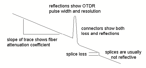
The slope of the fiber trace shows the attenuation coefficient of the fiber and is calibrated in dB/km by the OTDR. In order to measure fiber attenuation, you need a fairly long length of fiber with no distortions on either end from the OTDR resolution or overloading due to large reflections. If the fiber looks nonlinear at either end, especially near a reflective event like a connector, avoid that section when measuring loss.
In OTDR terminology, connectors and splices are termed "events" and should display loss; connectors and splices additionally exhibit a reflective peak, its height indicating reflection, unless excessive reflection saturates the receiver, resulting in a flat peak with a tail, indicating receiver overload. Occasionally, a good fusion splice might have minimal loss, evading OTDR detection, which benefits the system but can perplex operators. Knowing network fiber lengths is crucial to locate events accurately and navigate unexpected occurrences. Reflective pulses showcase OTDR resolution; events closer than pulse width are indiscernible. Longer pulses enhance distance visibility, while narrower pulses provide higher resolution at the expense of reduced range.
Understanding the physics and errors of the measurement
Don't let the title put you off, it's pretty basic. The amount of light scattered back to the OTDR for measurement is quite small, about one-millionth of what is in the test pulse, and it is not necessarily constant. This affects the operation and accuracy of OTDR measurements.
Measuring fiber, not cable distance
OTDRs measure fiber not cable length. While this may sound obvious, it causes a lot of problems in buried cable. You see, to prevent stress on the fiber, cable manufacturers put about 1% more fiber in the cable than the length of the cable itself, to allow for some "stretch." If you measure with the OTDR at 1000 meters (3300 feet), the actual cable length is about 990 meters (3270 feet). If you are looking for a spot where the rats chewed through your cable, you could be digging 10 meters (33 feet) from the actual location!
Auto-test programs
Never simply attach an OTDR to the cable plant and hit the "auto-test" button! We know of applications where that was done that cost the installers and users big headaches - and bucks! ODTRs are not smart enough to make the decisions on setup and pass/fail themselves - they are easily fooled. If you do the setup correctly yourself, you can try "auto-test" and see if it gives reliable results, but never use it without knowledgeable operator oversight.
Overload recovery
Due to limited light return, the OTDR requires a highly sensitive receiver circuit; significant reflections, even at one percent of the outgoing signal, can saturate and overload the receiver, causing unreliable traces until recovery. Notably, this issue frequently arises from the OTDR's own connector, leading to an "Dead Zone" recovery time of 50 meters to one kilometer (170 to 3000 feet), depending on OTDR design, wavelength, and reflection strength. A "pulse suppresser" cable, essentially a "launch" cable, offers recuperation time and initial cable plant insight; it is essential for OTDR use to avoid issues. This launch cable, ideally 500 to 1000 meters long, must feature high-quality connectors that match those being tested in the cable plant, aiding in reflection reduction.
Ghosts
Testing short cables with highly reflective connectors can result in confusing "ghosts". These ghosts stem from reflected light bouncing between far-end connectors until attenuation to noise level, mimicking real reflective events like connectors without showing any loss. To locate ghosts when an unexpected reflective event emerges where no connection should exist, examine multiples of the launch cable or first tested cable's length. Ghosts can be eliminated by minimizing reflections through a later-described method. Short cables can intensify this confusion with multiple reflections; an instance involved a short cable appearing faulty due to OTDR testing, wrongly indicating a mid-cable break caused by ghosted images, demonstrating the importance of reviewing distance scales.
Backscatter variability errors
A challenge arises from the backscatter coefficient, which denotes the light scattered back to the OTDR from the test pulse. The OTDR calculates loss based on diminishing returning light, yet merely one-millionth is scattered for measurement and is variable. Backscattered light relies on fiber attenuation and core diameter. Differing backscatter coefficients between connected fibers introduce errors in measuring splice or connector loss. If one fiber has higher loss than the other, backscattering discrepancies result in an error, inflating the displayed loss.
Conversely, transitioning from low to high loss fibers reduces backscatter, yielding underestimated loss or even a "gainer." A 0.1 dB per km difference in attenuation can yield a 0.25 dB splice loss error. This can be mitigated by reading in both directions and averaging measurements, common in many OTDRs. Diameter fluctuations, causing 1% diameter variation, lead to 0.1 dB backscatter differences, affecting tapered fibers and trace anomalies due to manufacturing inconsistencies.
Resolution limitations
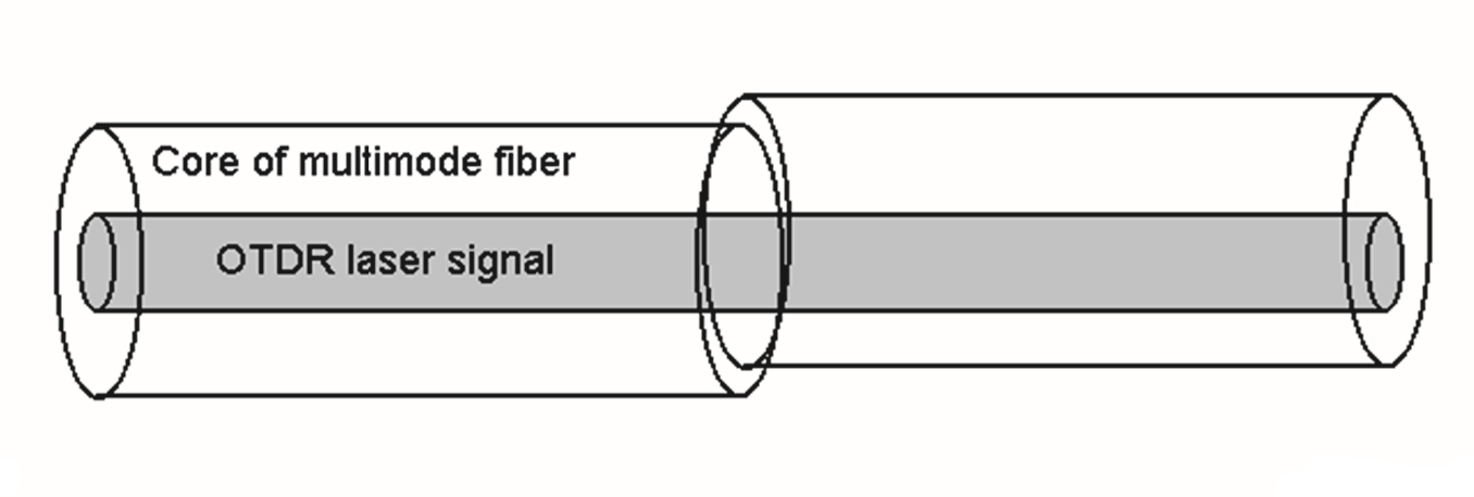
Special consideration for multimode fiber
OTDR measurements are commonly used for singlemode fiber in outdoor cables, while indoor cabling like campuses use multimode fiber with LED sources for lower speed networks. OTDR faces challenges with multimode fiber due to laser source use for higher backscatter levels. Laser light in multimode fiber is mainly confined to the core center, unlike LEDs which spread across the core. This results in lower connector loss due to minimized offset errors, and even the fiber loss is reduced as central core light travels a shorter path than the edges. Efforts to correlate OTDR, source, and power meter measurements for multimode fiber have been unsuccessful. Typically, OTDR measures 6-7 dB loss, while source and power meters show 10 dB for the same cable plant.
Conclusion
Optical Time-Domain Reflectometers are vital tools for maintaining and troubleshooting fiber optic networks. By following the steps outlined in this guide and adhering to best practices, you can harness the power of the OTDR to accurately assess the quality of optical fibers, locate faults, and ensure the optimal performance of your fiber optic infrastructure. As technology continues to evolve, mastering the art of using an OTDR remains an essential skill for professionals in the field of optical communications.
DINTEK's Optical Time Domain Reflectometer

- 7-inch TFT color LCD display, touch screen
- External interfaces USB, MICRO-USB
- Maximum 45dB large dynamic range
- 128k data sampling points
- High-ranging resolution of 0.05m
- ≤0.8m ultra-short event blind zone
- PON network Online test
- Penetrate optical splitter up to 1:8 / 1:64
- Test each branch of the PON network accurately
- Feature: OTDR, Event Map, OPM, OLS, VFL, (Microscope Optional)
- Automatic detect and alarm of incoming optical signals
- Optical output interface FC/SC/ST
- Built-in High Capacity lithium battery
- Battery operating time: > 12h
- Supports variety language interfaces: Chinese, English, Spanish, French, German, Italian, Portuguese, Russian, Koeran, etc.
Visit the product page here or please contact


