

An installer-focused guide to cabinet layout, structured cabling, power, airflow, resilience and administration.
Introduction
A data center cabinet is much more than a 19-inch enclosure for servers and network equipment. It is where structured cabling, switching, power distribution, cooling, bonding and day-to-day administration come together.
A cabinet can look tidy yet still be difficult to maintain, thermally inefficient or poorly prepared for growth. The decisions made before equipment is installed have a direct influence on connectivity, serviceability and the ability to accommodate future requirements.
This guide outlines the key considerations for planning and installing a data-center-style cabinet. It covers cabinet selection, cabling architecture, copper and fiber connectivity, airflow, power resilience, cable management, testing and documentation, with examples of how DINTEK solutions can support a modular installation.
Important standards note: This guide is an implementation aid, not a substitute for official standards, local electrical regulations, fire codes, equipment manufacturer requirements or project specifications. Confirm the applicable standards editions and project requirements during the design process.
Choose the Right Cabinet and Plan the Layout
Before deciding where patch panels and switches should sit, establish the cabinet’s function within the wider network. The equipment mix determines the required dimensions, airflow, patching density, power architecture and capacity for future expansion.
Common cabinet roles include:
Server cabinet: Primarily compute and storage equipment.
Network cabinet: Switching equipment, fiber connectivity and high-density patching.
Distribution cabinet: Passive patching, cross-connects and backbone terminations.
Mixed cabinet: A combination of active equipment and structured cabling.
Carrier or service cabinet: Service-provider, demarcation or edge equipment.
The cabinet should support its intended role within the data center’s telecommunications topology, rather than being treated as a standalone furniture decision.
CONSIDER DIMENSIONS, ACCESS AND CAPACITY
A 42U cabinet is common, but taller cabinets may provide useful additional capacity where room height, access and loading permit. Avoid designing a layout that consumes every rack unit from day one.
Depth is equally important. Modern servers and switches need space for chassis, rear connectors, power plugs, cable routing, fiber bend radius, vertical power distribution units (PDUs) and exhaust airflow. Cabinet dimensions must accommodate the actual equipment and its service requirements.
Width affects cable-management capacity. Wider cabinets can provide additional side space for dense cabling, but the appropriate dimensions depend on the cabinet’s role, applicable standards and project design.
Also check equipment and cabinet load ratings, floor loading, door openings, side-panel access, aisle clearances and the delivery route before equipment arrives.
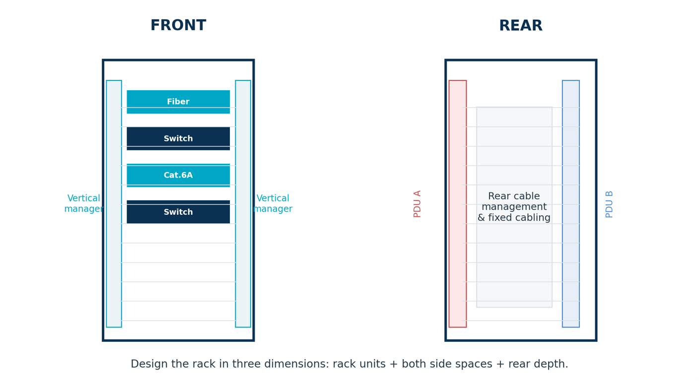
DESIGN IN THREE DIMENSIONS
A rack elevation shows the front of the cabinet, but a workable installation also needs adequate side and rear space for fixed cabling, patch cords, PDUs and airflow.
Plan cable routes and service access before equipment is installed. Reserve space for vertical and horizontal cable managers, and make sure cable density will not obstruct access to connectors or interfere with active equipment.
Installer rule: Spare rack units alone do not make a cabinet expandable. Allow headroom in cable managers, fiber positions, patch-panel capacity, switch ports, PDU outlets and pathways as well.
Plan Airflow, Power and Resilience
Cabinet design must account for how equipment is cooled and powered, as well as how services will be maintained if a component or supply fails.
PROTECT AIRFLOW
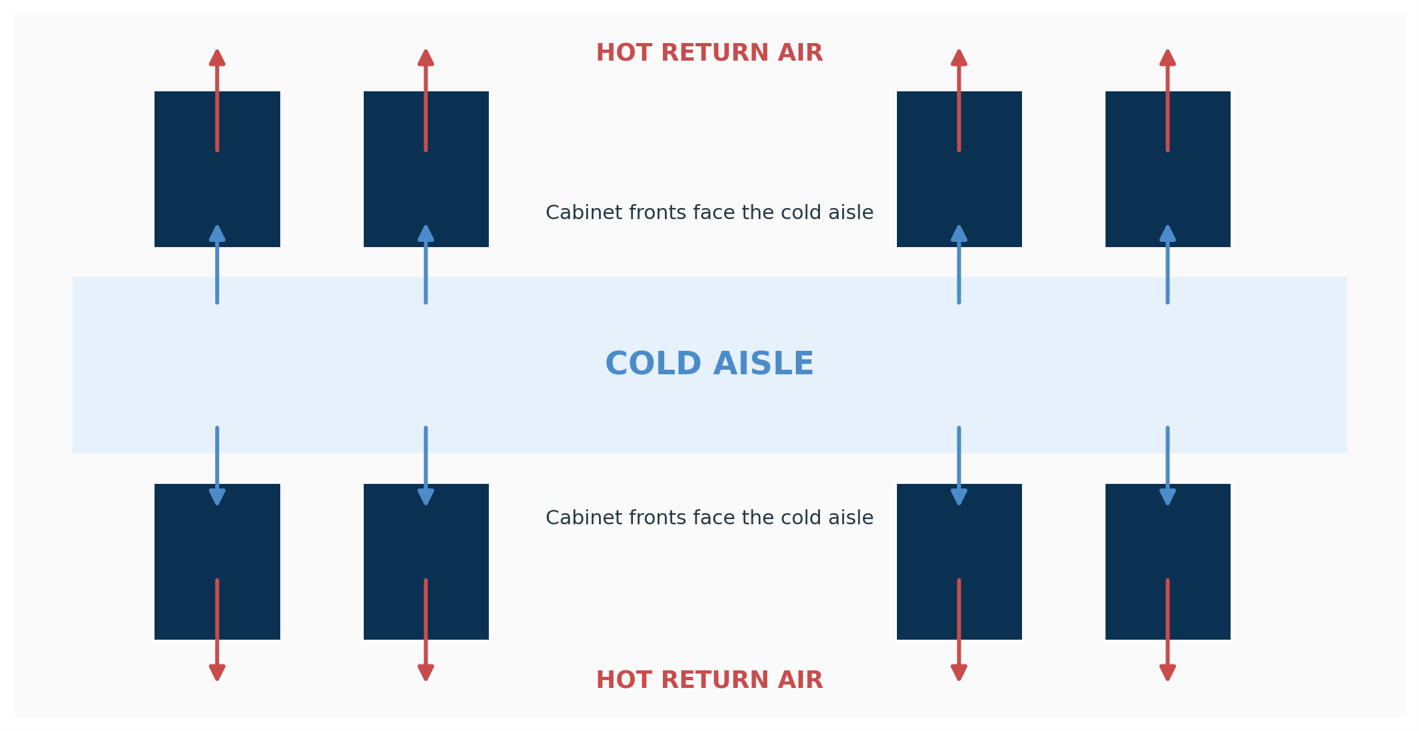
Most air-cooled IT equipment is designed for front-to-rear cooling. Cabinet orientation and cable routing should support the data center’s hot-aisle/cold-aisle arrangement and avoid recirculation paths.
Practical considerations include:
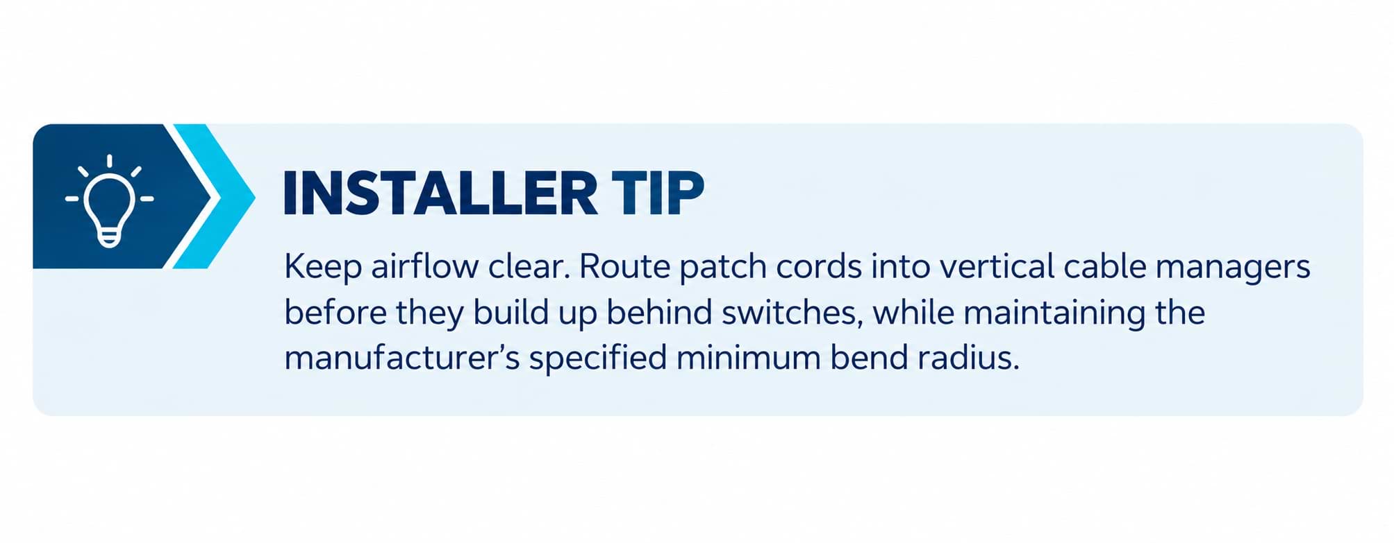
Route patch cords towards side cable managers rather than allowing large bundles to build up behind fans.
Avoid coiling excess copper or fiber behind switches and servers.
Use doors appropriate to the equipment’s airflow requirements.
Fit blanking panels in unused rack units where required by the cooling design.
Ensure rear cable trays, PDU cords and trunk loops do not obstruct equipment exhaust.
A neatly dressed cable bundle can still cause a thermal problem if it sits directly across the exhaust of a high-density switch. Cable routing must support airflow first.
Simplified hot-aisle/cold-aisle arrangement. Cabinet fronts face the cold aisle; exhaust is discharged to the hot side.
PLAN POWER DISTRIBUTION AND A/B RESILIENCE
Power requirements should be agreed with the electrical or data center designer before the cabinet is populated. Consider expected and maximum equipment loads, circuit and PDU capacity, outlet types, UPS architecture, redundancy objectives and future growth.
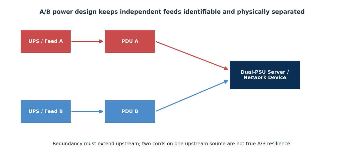
Where the project requires A/B power resilience, dual-power-supply equipment may connect to separate PDU A and PDU B feeds. These feeds must remain independent to the level required by the design. Two rack PDUs connected to the same upstream circuit or UPS do not, by themselves, provide true A/B redundancy.
Keep A and B feeds identifiable, coordinate power-cord lengths with equipment positions, and maintain the required separation between power and telecommunications cabling.
Conceptual A/B power arrangement for dual-power-supply equipment
CONSIDER NETWORK-PATH RESILIENCE
Two network connections do not automatically create a resilient design. If both connections share a patch panel, cable tray, cabinet entry, switch or upstream pathway, a single event may still interrupt both. Trace each required network path through the physical infrastructure and identify common points of failure. The appropriate degree of separation depends on the project’s availability and resilience objectives.
Power resilience and network resilience should be coordinated, but they are separate design considerations.
Design the Structured Cabling Architecture
A maintainable cabinet separates the permanent cabling infrastructure from the patch cords used to connect active equipment. Fixed cabling should remain in place when switches, servers or other devices are replaced, allowing changes to be made at designated patching points.
A typical structured connection may follow this path:
Switch → Patch panel → Fixed or trunk cabling → Patch panel → Equipment patch cord → Server
The exact arrangement depends on the network architecture and project requirements. Fixed cabling, patching fields and cross-connects should be planned before installation rather than improvised as equipment is mounted.
CHOOSE THE SWITCHING ARCHITECTURE EARLY
Top-of-rack (ToR) switching places switches close to the servers they serve, allowing short server-to-switch connections. It can reduce large copper cable bundles between cabinets, but may increase the number of distributed switches and the density of fiber uplinks.
End-of-row or middle-of-row switching can consolidate active equipment in fewer locations, but may require more horizontal cabling, larger patching fields and additional pathway capacity.
Neither arrangement is universally preferable. The decision should be made during network design because it affects cabinet space, patch-panel quantities, cable routes and power requirements.
Architecture | Typical Benefits | Typical Design Consequences |
|---|---|---|
Top-of-Rack (ToR) | Short server-to-switch connections; reduced large copper bundles between cabinets. | More distributed switches, power and management; higher fiber uplink density. |
End-/Middle-of-Row | Consolidated switching; fewer active switch locations in some designs. | More horizontal cabling, larger patching fields and more demanding pathways. |
MANAGE FIXED CABLING AND PATCH CORDS SEPARATELY
Route permanent cabling securely to the designated termination and support areas. Keep patch cords accessible and traceable so technicians can make changes without disturbing the fixed infrastructure.
Avoid using a single patch-cord length throughout the cabinet simply for purchasing convenience. A controlled range of lengths helps reduce excess cable, congestion and obstruction of equipment airflow.
Plan Copper and Fiber Connectivity
Copper and fiber serve different roles within a data center. Their selection should reflect application requirements, link distances, equipment interfaces, network architecture and the expected migration path.
COPPER CONNECTIVITY
Where 10GBASE-T is required over balanced copper cabling, Category 6A is a common choice. The selection of unshielded or shielded components should follow the project specification, electromagnetic compatibility requirements, bonding design and the capabilities of the installation team.
DINTEK PowerMAX+ Category 6A components can be used to build a matched copper channel using the specified cable, outlets, patch panels and patch cords. Straight or angled panels may be selected according to the cabinet’s cable-management strategy.
High port density can save rack space, but it must not come at the expense of finger access, clear labelling, cable bend radius or the ability to make future changes.
FIBER SELECTION AND ROUTING
Fiber supports backbone links, switch uplinks, storage networks and high-speed connections within modern data center fabrics.
Common options include OM4 and OM5 multimode fiber and OS2 single-mode fiber. The appropriate choice depends on application reach, transceiver strategy, link requirements, migration plans and lifecycle cost. Avoid selecting fiber solely around the transceivers being installed today.
When planning fiber infrastructure:
- Reserve spare fibers in backbone and trunk designs.
- Confirm connector types, polarity methods and compatibility with the intended applications.
- Protect fiber from excessive tension and bends beyond specified limits.
- Provide dedicated slack-management locations rather than loose coils.
- Inspect and clean connector end faces before mating.
USE MODULAR CONNECTIVITY WHERE IT MAKES SENSE
Modular panels and cassette systems can simplify changes to dense copper and fiber installations by creating organised, accessible termination points.
DINTEK’s ezi-PANEL range provides a cassette-based approach to presenting copper and fiber connections within a panel. The 1U eight-slot ezi-PANEL, part number 2201-08001, supports compatible fiber and RJ45 cassette options, subject to the current product specification. MaxiFIBER solutions can also be considered where higher fiber density is required.
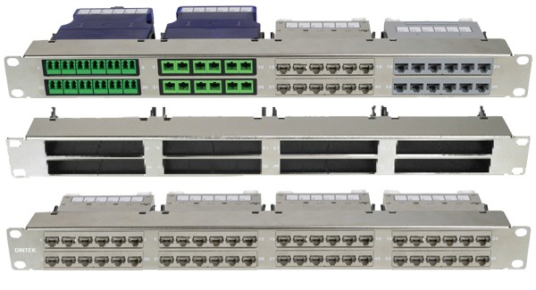
1U Blank 8 Slot ezi-PANEL for Fiber & Copper Cassettes
ALLOW FOR SPINE-AND-LEAF NETWORKS
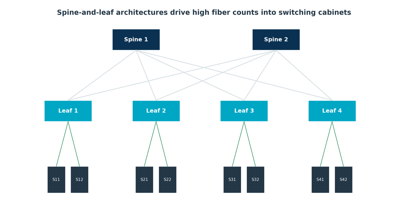
Simplified spine-and-leaf topology. The inter-switch mesh can drive high fiber counts into network cabinets.
Spine-and-leaf architectures can create a high concentration of fiber connections within switching cabinets. In this topology, leaf switches connect to spine switches, and the resulting inter-switch fabric can require many high-speed links even when the cabinet contains relatively few servers.
Modular trunk cabling and MPO/MTP-based systems can help organise these connections and reduce field termination work. High-density LC presentation may also be appropriate, depending on the required connector count, fiber type and polarity method. Product selection should be based on the actual design and verified against current datasheets.
Build in Cable Management and Bonding
Cable management should be designed into the cabinet from the beginning. It is not simply a finishing task after the equipment is installed.
Use suitable vertical and horizontal cable managers, route permanent cabling securely, and keep patch cords accessible for maintenance. Plan cable entry points and rear support so that cable bundles do not obstruct airflow or make equipment difficult to service.
Fiber routing requires particular care. Maintain the specified bend radius, avoid excessive tension and provide suitable slack management. Keep connectors accessible for inspection and cleaning.
BOND THE CABINET CORRECTLY
Cabinets and other conductive telecommunications infrastructure must be incorporated into the project’s bonding system in accordance with applicable standards, local electrical requirements, the cabinet manufacturer’s provisions and the project design.
For shielded copper systems, shielding, patch panels and bonding should be treated as parts of a complete engineered system. Do not improvise bonding paths through painted mechanical joints. Verify and document continuity where required by the project.
Bonding and electrical work must be undertaken by appropriately qualified personnel in accordance with the applicable requirements.
Design for Growth and Future Changes
A future-ready cabinet needs more than a few empty rack units. It must have sufficient space and capacity to accommodate additional connections, equipment and pathways without requiring major rework. A useful design test is:
Can another 24 connections be added without dismantling what is already live?
If the answer is no, the cabinet may already be effectively full even if rack units remain available.
Consider future capacity for:
Rack units and equipment service space.
Patch-panel and cassette positions.
Spare trunk fibers and switch ports.
Vertical and horizontal cable-management capacity.
Cable trays and pathways.
PDU outlets and electrical capacity.
Cooling capacity and airflow.
Documented rack-unit reservations.
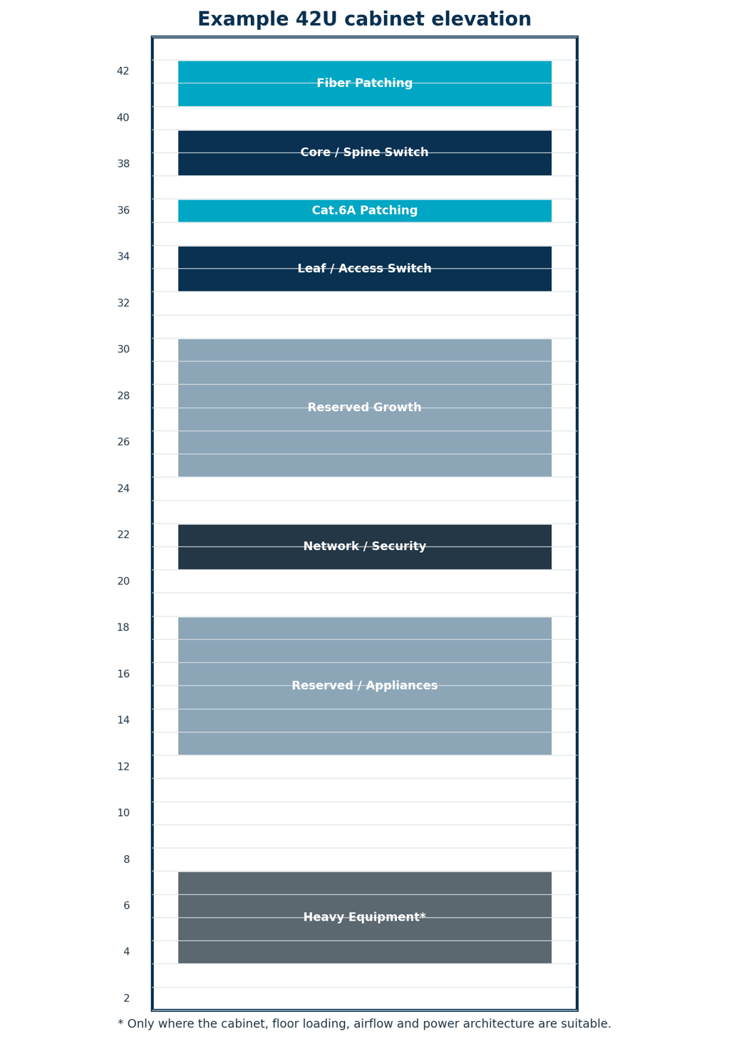
The 42U layout is an example of the planning principle, not a universal cabinet arrangement. Actual placement must be determined by equipment dimensions, loading, access, thermal requirements and the project’s power and cabling architecture.
Test, Commission and Document
A cabinet is not ready for service simply because the last patch cord has been connected. Testing and documentation should be planned before installation begins, with results linked to the identifiers used on the finished infrastructure.
TEST COPPER AND FIBER
For copper, complete the permanent-link or channel testing required by the project specification and applicable cabling standard. Verify the required performance parameters and store electronic results against the corresponding link identifiers.
For fiber, check end-to-end continuity and polarity, perform insertion-loss testing as specified, and use OTDR testing where required by the project. Inspect and clean connector end faces before final connection, and record fiber/core identifiers and trunk and cassette endpoints.
LABEL AND DOCUMENT THE INSTALLATION
Every important component should have a logical identifier linked to the site’s records. Depending on project scope, this may include the cabinet, rack-unit position, patch panel and port, fiber cassette and adapter, trunk link, switch port, PDU outlet and power feed.
For example: DC1-HDA02-R07-PP03-17
This could represent Data Center 1, Horizontal Distribution Area 02, Rack 07, Patch Panel 03, Port 17. The naming convention should be agreed with the project team rather than adopted without reference to the site’s existing system.
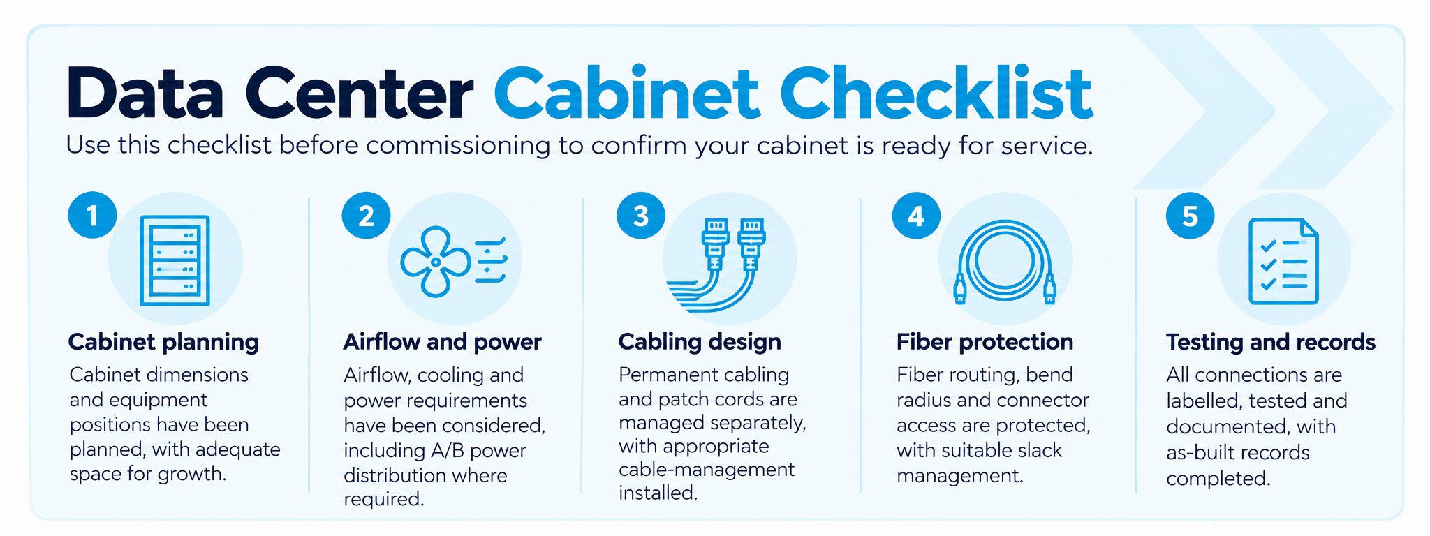
Relevant Standards
Data center cabinet and cabling designs should align with recognised standards and the requirements of the specific project. The following references are relevant to different aspects of the infrastructure discussed in this guide.
ANSI/TIA-942-C:2024 — Data Center Telecommunications Infrastructure
This standard addresses data center infrastructure, including telecommunications spaces, cabling, pathways, redundancy, installation, grounding and bonding, administration and related facility considerations.
ISO/IEC 11801-5:2017 — Generic Cabling for Data Centres
This standard addresses generic cabling within data center spaces, including structured cabling architecture and transmission channels.
ISO/IEC 22237-3:2021 — Power Distribution
This part addresses power distribution aspects of data center infrastructure, including considerations relevant to telecommunications bonding.
ISO/IEC 22237-4:2021 — Environmental Control
This part addresses environmental control, including cooling, temperature and humidity conditions that affect data center operation.
Always verify the current status and applicable editions of standards, together with local electrical and fire requirements, manufacturer instructions and project specifications. These references provide orientation and do not replace the official standards.
ISO/IEC TS 22237-5:2018 — Telecommunications Cabling Infrastructure
This part of the ISO/IEC 22237 series addresses telecommunications cabling infrastructure, including computer-room cabling, fixed cabling, pathways, spaces, enclosures and cable-management considerations. Confirm the applicable edition and status when planning a new project.
Build for What Comes Next
A data center cabinet should be designed as an integrated infrastructure system, not simply a metal enclosure filled with equipment. The strongest designs coordinate structured cabling, airflow, power, bonding, resilience, administration and future expansion before installation begins.
Careful planning can make the cabinet easier to install, maintain and upgrade as equipment and network requirements change. Adequate space, controlled patch-cord lengths, modular connectivity, clearly identified power and network paths, and complete test records all contribute to a more serviceable installation.