Grounding and Bonding within a Telecommunications System
Grounding and bonding is an essential practice within a traditional electrical installation, and it is also required within a telecommunication network system. Telecommunications grounding and bonding is not a replacement for the requirements within the National Electrical Code (NEC), but is an additional installation specifically for the telecommunication system's performance.
The ANSI/TIA/EIA-607 standard is the commercial building grounding and bonding requirements for telecommunications with the primary objective of providing guidance around the issue of bonding and grounding as it relates to building telecommunications infrastructure.
The standard defines a telecommunications grounding and bonding system and outlines the interconnections to the building electrical grounding system.
As noted above, the recommendations made in this standard do not supersede the bonding and grounding requirements of national and local electrical code. As electrical equipment is so sensitive, simply grounding to structural steel isn't enough for a telecommunication system. All of the cabling and power used needs to be effectively equalised to prevent loops or transients that could damage equipment, therefore, a complete grounding and bonding system is required to accommodate these constraints.
A Telecommunications Grounding and Bonding System (pictured right) starts with a physical connection to the building grounding electrode system and extends to every telecommunications room (TR) in the building.

Telecom Main Grounding Busbar (TMGB)
Telecom Bonding Backbone (TBB)
Telecom Grounding Busbar (TGB)
Telecom Bonding Backbone Interconnecting Bonding Conductor (TBBIBC)
Telecommunications Grounding System Components
Telecommunications Entrance Facility (TEF)
The Telecommunications Entrance Facility (TEF) includes the entrance point at the telecommunications service and also the space where the inter- and intra-building backbone facilities join. Telecommunication-related antenna entrances and electronic equipment may be located in the TEF.
Telecom Bonding Conductor
The ANSI/TIA/EIA-607 standard requires that all Telecom Bonding Conductors be listed for the intended purpose and approved by a nationally recognised testing laboratory such as UL or ETL.
Bonding Conductors must always be insulated wires and made of copper metal. Other metal types are not supported for use under the current standard. The minimum size of all Bonding Conductors must be at least a No. 6 AWG wire.
The standard prohibits placing bonding conductors in a metallic conduit made of iron. If the Bonding Conductor must be placed in an iron conduit longer than 1m (3 ft.) in length, then it must be bonded at each end of the conduit. The wires used for this must again be at least a No. 6 AWG wire.
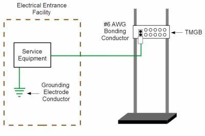
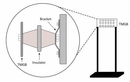
Telecom Main Grounding Busbar (TMGB)
The TMGB is the dedicated extension of the building grounding electrode system for the telecommunications infrastructure. Because it is the central attachment point for TBBs and equipment, the TMGB should provide easy access for telecommunications personnel.
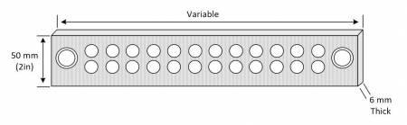
The TMGB is a pre-drilled copper busbar with standard NEMA bolt-hole sizing and spacing for the particular lug connection that will be used. It should be large enough to satisfy today's applications and accommodate future growth. A minimum of 6mm thickness and 100mm width is required. Many varieties of ground bars are available, and some come as a kit and can be customised to meet the specific requirements of the application. Pre-welded CADWELD pigtails are available in a variety of conductor sizes and lengths, insulated or bare, ready to be attached to the building ground
For reduced resistance, electrotin plating is preferred. However, if not plated, the mating surfaces must be completely cleaned. Where telecommunications panelboards are located with the TMGB, they must have the alternating current equipment ground bus (or a metallic enclosure) bonded to the TMGB/TGB. All appropriate clearances should be maintained while locating TMGBs as close as possible to the panelboards.
Connections to the TMGB or lugs should be exothermic welds. Exothermic welds provide a connection that helps ensure the long-term integrity of the grounding system.
Telecom Bonding Backbone (TBB)
The TBB is a conductor that connects all TGBs with the TMGB. It reduces or equalises potential differences between the telecommunications systems to which it is bonded. The TBB should not be the only conductor that provides a ground fault current return path.
Starting at the TMGB, the TBB loops throughout the building via telecommunications backbone pathways. It connects TGBs in every telecommunications closet and equipment room within the building. Multiple TBBs may be necessary, depending on the size of the structure and the number of TGBs in the building. Water pipes or metallic cable shield should not be used as telecommunications bonding backbone.
Each TBB should be an insulated copper conductor, a minimum of No. 6 AWG and possibly as large as 750 kc mil often used by telephone and communications companies. In a multi-story building where more than one TBB is used, the TBBs must be bonded together with a TBB Interconnection Bonding Conductor (TBBIBC) located on the top floor and at least every third floor.

Telecom Grounding Busbar (TGB)
A TGB is a pre-drilled copper busbar with standard NEMA bolt hole sizing and centrally connected systems and equipment served by a telecommunications closet. It should be at least 6mm thick by 50mm wide. Just like the TMGB, the TGB should be electrotin-plated or cleaned prior to connecting the conductors to the busbar. The bonding conductor between the TBB and the TGB should be continuous and run in the most direct path possible.
Often the TGB is installed to the side of the panelboard. When the building's structural steel is effectively grounded, each TGB should be bonded to the steel within the same room with a No. 6 AWG conductor. Always use the shortest distance possible in the grounding system.
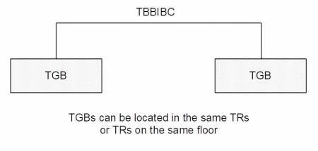
Telecom Bonding Backbone Interconnecting Bonding Conductor (TBBIBC)
The ANSI/TIA/EIA-607 standard requires that when two or more TBBs are installed vertically in the intrabuilding backbone pathway, the TBBs must be bonded together. The Telecommunications Bonding Backbone Interconnecting Bonding Conductor (TBBIBC) is the component used for this function.
The TBBIBC must be installed at the top floor and a minimum of every third floor. The minimum size of the TBBIBC must be no smaller than the TBB conductor size.
The TBBIBC would also be used to bond two or more TGBs installed in the same TR together. The TBBIBC is also used to bond the TGBs installed in different TRs that reside on the same floor of the building. This connection would follow the same requirements as bonding multiple TBBs at the top floor and a minimum of every third floor.